Fill the Form

Cable Trays
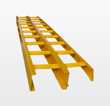
FRP Ladder Cable Tray
Cable trays serve as an effective support system for organizing and managing cables in buildings and other settings. Installing cable trays allows for easy maintenance and replacement of cables without hassle. They provide excellent ventilation, which helps extend the lifespan of cables. We offer high-strength ladder-type cable trays, designed for heavy-duty power distribution in industrial applications.
Advantages
- Efficient Cable Management
- Ease of Maintenance
- Enhanced Airflow
- Heavy-Duty Durability
- Versatility in Installation
| Ladder Type Cable Tray | |||
|---|---|---|---|
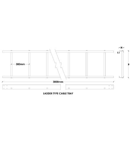
| W | H | T | |
| 1 | 100mm | 30mm | 3mm |
| 2 | 100mm | 30mm | 4mm |
| 3 | 200mm | 30mm | 3mm |
| 4 | 100mm | 50mm | 3mm |
| 5 | 150mm | 50mm | 3mm |
| 6 | 300mm | 75mm | 4mm |
| 7 | 450mm | 75mm | 4mm |
| 8 | 600mm | 100mm | 4mm |
| 9 | 750mm | 100mm | 4mm |
SR : FRP Ladder Cable Tray
| 75mm X 3mm/4mm Channel Size | 300mm to 1000mm Width Runner |
| 100mm X 3mm/4mm Channel Size | 300mm to 1000mm Width Runner |

Plexxe Composite Cable Tray Specification
 STANDARDS APPLICABLE
IS 6746 - 1994 Specs for Unsaturated Polyester Resin systems for Low Pressure Fiber Reinforced Plastics.
NEMA FG 1 1984- 1993 (current issue) Specifications for fiberglass Tray System-Loading Characteristics.
IS 6746-Appendix-K/UL 94 Flame Retardant (law flammability/V0).
 TECHNICAL DETAILS
Side Member FRP Pultruded 'C' Section.
Rung Sq. Hollow tube 25mm X25mm.
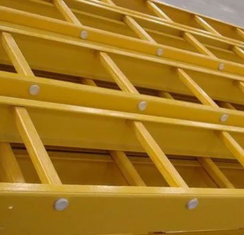
Construction/assembly of tray. The rungs to side member are connected, will have both mechanical & adhesive lock. The tray shall be assembled by use of a locking pin made of fiberglass reinforced thermoplastic. The locking pin is inserted under pressure by machine with a high strength adhesive. All the bonded parts are surface prepared for maximum adhesion. All straight sections are pre drilled for Coupler plates. All cut ends shall be resin coated.
Length of Cable Tray 3000mm, 6000mm.
Width of cable Tray 150mm/ 300mm/ 450mm/ 600mm/ 750mm/900mm.
Rung Spacing 250mm/300mm.
Radius of Fittings 300mm, 600mm, 900mm.
Material of Side Member & Rung Corrosion Resistant Polyester-Isophthalic / vinyl ester, Flame Retardant U.V. Stabilized Resin System and Various types of Glass Fiber. Minimum Glass Content 55 to 60% in all pultruded sections and 30 to 40% for at sheets and other molded parts.
Ultra Violate Radiation protection : All the composite materials shall have UV Light inhabiting chemical additives to resist degradation from UV.
Flame Retardancy All the composite material shall be retardants & will have flame spread of 25 or less (Class 1Rating) when tested in accordance with ASTM D 635. Pultruded parts are provided with surface veil to achieve maximum chemical resistance.
 ACCESSORIES/FITTINGS.
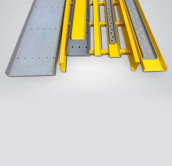
All Fittings are pre fabricated & will be same specification as of straight trays.
 CONNECTION / COUPLER PLATE & SPLICE PLATES
FRP / Stainless steel Splice plates of various types ie.straight as well as adjustable for angles. This plates should be installed between 0.2 & 0.3 of the length of span of the support. Fastner of SS 304 / SS 316 shall be provided of 6mm/8mm diameter.
 TYPICAL PROPERTIES OF PULTRUDED SECTIONS
ASTM-D-2863-Oxygen Index-30%.
ASTM-D-635 - Flame Spread (Extent of burning) - 25 mm.
ASTM-D-638 -Tensile Strength at break - 30,000 PSI.
ASTM-D-790 - Flexural Strength at break - 30,000 PSI.
ASTM-D-256 - Izod Impact Strength - 25 Ft.-LBS.
ASTM-D-149 - Electric Strength short terms Oil - 35 Kv/inch.
Surface Resistivity - >1012 Ω.
 CORROSION RESISTANCE OF RESIN SYSTEM
Two standard composites resin systems are available. For most of the application polyester Fire retardant (FR-P) is widely used. A vinyl ester composites re retardant resin system (FR-VE) is used where strong acide (like hydrochloric acid), strong alkalis (like Caustic Soda), organic solvents and halogenated organic conditions exist. Plexxe Composite cable tray incorporates a synthetic veil on the surface of all structural shapes which causes a resin rich layer which enhances corrosion protection. An abbreviated guide can be provided on request to assist in the selection of the proper resin system for individual application.


